
Metal Core PCB is a IMS insulated metal substrate to improved thermal conductivity and heat dissipation. The manufacturing process is similar to that of ordinary PCBs. Generally there are no more than four layers, and most of them are single-sided. Commonly used metal materials are aluminum, copper, iron.
SEEKPCB is capable of most of the metal core PCB types, multilayer Metal core PCB with metal plate by side or in the middle, else, Blind hole, Blind slot and every kind of heat sink supportive solutions are achievable here in SEEKPCB.


-
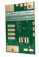
 Aluminum Printed Circuit BoardsRead MoreAluminum Printed Circuit Boards are widely used in LED lighting, power supply, they are the most cost-effective and most widely used type of metal substrate.
 -
 Copper Metal Core PCBCopper Metal Core PCBs have better thermal conductivity, but they are difficult and expensive to produce, and are generally used in higher power lighting and power supplies.Read More
 -
 Iron metal Core PCBIron metal Core PCBs has advantages with its magnetic permeability, acid & alkali & moisture resistance. generally come in the form of stainless steel, which is generally used in high humidity scenarios.Read More


| Subject | Our Capability |
|---|---|
| Metal Type | Aluminum(1100/3003/5052/6061), Copper(C11000), Iron(Stainless) |
| Thermal Conductivity | In Stock 1-8W/(m·K), Max 15 W/(m·K) |
| Layer | 1-12L |
| Structure | Metal Base PCB, Metal Core PCB(Sandwiches), Copper BUMP(Thermoelectric separation) |
| Copper Thickness | 1OZ - 12OZ |
| Total Thickness | 0.5 - 10mm |
| Insulating layer thickness | 100,125,150,200um |
| Max. board Dimension | 600*1500mm |
| Min Hole Diameter | 0.8mm(npth)/0.3mm(pth) |
| Min. line width/spacing | 75um/75um |
| Special Hole | Blind Hole, Blind Slot, T-Hole, T-Slot, Counter Sink Hole, Cup Hole |
| Surface treatment | OSP, ENIG,Plating Silver, ENEPIG, Immersion Silver, Immersion Tin |
| Outline | Tooling Punching, CNC Routing, V-CUT, Laser Routing +/-0.1mm |
-
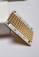
 Copper bump
 -
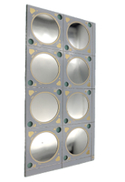
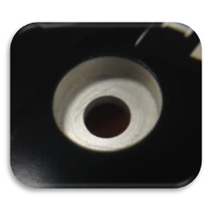
 Concave Cup
 -
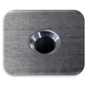 Countersink Hole
 -
 Blind Routing
 -
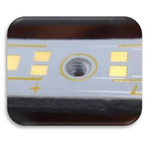 Screw Hole Tapping
 -
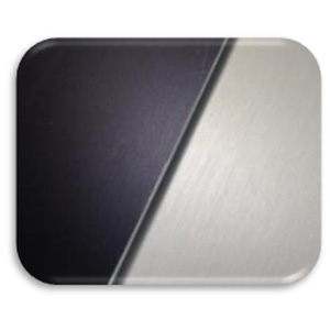 Anodic Treatment


Why Choose SEEKPCB as Your Metal Core PCB Partner
What is Metal Core PCB
A Metal Core PCB (MCPCB), also known as a ims insulated metal substrate, is a type of printed circuit board that is made using a metal core as its base material. Unlike standard printed circuit boards, which are made using insulating substrates like fiberglass or ceramic, MCPCBs use a metal core, typically made of aluminum, copper or another metal alloy, as the base material.
The metal core provides several benefits, including improved thermal conductivity and heat dissipation, which makes MCPCBs ideal for applications that require high power and generate a lot of heat, such as high-power LED lighting, power electronics, automotive, and aerospace industries. The metal core also provides mechanical support and protection to the circuit components mounted on the board.
The ims insulated metal substrate is typically laminated with a dielectric material, such as a thermally conductive epoxy or polyimide, on both sides. The dielectric layer insulates the metal core from the copper traces and other components mounted on the board. The copper traces and other components are then added to the board using standard PCB manufacturing processes.
The metal core can be either a solid sheet or a thermally conductive pre-preg layer that is laminated between two metal sheets. The thickness of the metal core and dielectric layer can vary depending on the specific requirements of the application.
The ims insulated metal substrate come in various types, including aluminum printed circuit boards (with aluminum plate) , copper metal core pcb(with copper plate).
The Metal core PCB material
The metal core in Metal Core PCBs (MCPCBs) is typically made of aluminum, copper, or another metal alloy. The choice of material depends on the specific application and requirements of the board.
Aluminum is the most common material used for MCPCBs, as it provides good thermal conductivity and is lightweight, making it ideal for high-power applications. It is also a relatively low-cost material, which can help to reduce the overall cost of the PCB.
Copper is another popular material used for MCPCBs, particularly in applications that require higher thermal conductivity than aluminum can provide. Copper has a higher thermal conductivity than aluminum, which makes it ideal for applications that generate a lot of heat, such as power electronics and automotive systems.
Other metal alloys can also be used as the metal core in MCPCBs, depending on the specific application and requirements. For example, nickel-iron alloy cores can be used for applications that require high magnetic permeability.
In addition to the metal core, MCPCBs also include a dielectric layer, which is typically made of a thermally conductive material, such as epoxy or polyimide blending with ceramic. The dielectric layer provides insulation between the metal core and the copper traces and other components mounted on the board.
The thickness of the metal core and dielectric layer can vary depending on the specific requirements of the application. Thicker metal cores and dielectric layers provide better thermal performance but also increase the cost of the board.
Overall, the choice of metal core material is an important consideration in the design of MCPCBs and depends on the specific requirements of the application.
The advantages of Metal core PCB?
Metal Core PCBs (MCPCBs) offer several advantages over traditional printed circuit boards (PCBs) and other substrate materials. Some of the key advantages of MCPCBs include:
High Thermal Conductivity: MCPCBs have a metal core that provides excellent thermal conductivity, which makes them ideal for high-power applications that generate a lot of heat. The metal core helps to dissipate heat generated by the components, which improves their performance and reliability.
Better Mechanical Strength: The metal core in MCPCBs provides better mechanical strength compared to traditional PCBs and other substrate materials. This makes MCPCBs more durable and resistant to stress, bending, and other mechanical forces.
Improved Electrical Performance: MCPCBs offer better electrical performance compared to traditional PCBs and other substrate materials. The metal core provides a solid ground plane, which helps to reduce noise and interference in high-frequency applications.
Smaller Size and Weight: MCPCBs are typically smaller and lighter compared to traditional PCBs, which makes them ideal for applications where space is limited, such as in automotive and aerospace applications.
Cost-Effective: While MCPCBs may be more expensive compared to traditional PCBs, they are cost-effective in high-power and high-temperature applications, where they can improve the performance and reliability of the system, and reduce maintenance costs over time.
What are the typical structures of Metal core pcb?
The typical structures of Metal Core PCBs (MCPCBs) can vary depending on the specific application and the requirements of the designer. However, there are a few common structures that are commonly used in MCPCBs. These include:
Single Layer MCPCB: A single layer MCPCB consists of a metal core (usually aluminum or copper) with a single layer of dielectric material on top. The copper layer is then etched to create the circuit traces and pads, and a solder mask is applied to protect the circuitry.
Double Layer MCPCB: A double layer MCPCB consists of a metal core with two layers of dielectric material on top. The copper layers are then etched to create the circuit traces and pads, and a solder mask is applied to protect the circuitry. The two layers can be connected using vias or through-hole technology.
Multilayer MCPCB: A multilayer MCPCB consists of a metal core with multiple layers of dielectric material and copper layers. The layers are laminated together using a heat and pressure process, and the copper layers are then etched to create the circuit traces and pads. The layers are then interconnected using vias or through-hole technology, and a solder mask is applied to protect the circuitry.
Hybrid MCPCB: A hybrid MCPCB combines the properties of MCPCBs and traditional PCBs. It typically consists of a metal core with multiple layers of dielectric material and copper layers on both sides. The copper layers are then etched to create the circuit traces and pads, and the layers are interconnected using vias or through-hole technology. This type of structure can offer the benefits of MCPCBs for thermal management and high-power applications, while also offering the design flexibility of traditional PCBs.
The structure of an MCPCB will depend on the specific requirements of the application, the thermal and electrical properties of the materials, and the design constraints of the designer.
Metal Core PCB Applications
Metal Core PCB is used in a variety of applications, particularly in applications that require high power and generate a lot of heat. Some of the most common applications of Metal Core PCB include:
LED Lighting: Metal Core PCB are commonly used in high-power LED lighting applications, such as street lighting, automotive lighting, and industrial lighting. The high thermal conductivity of the metal core helps to dissipate heat generated by the LEDs, which helps to improve their reliability and lifespan.
Power Electronics: Metal Core PCB are also used in high-power electronics applications, such as motor drives, power supplies, and inverters. The high thermal conductivity of the metal core helps to dissipate heat generated by the high-power components, which helps to improve their performance and reliability.
Automotive: Metal Core PCB are used in automotive applications, such as electronic control units (ECUs) and LED lighting systems. The high thermal conductivity of the metal core helps to dissipate heat generated by the components, which helps to improve their reliability and lifespan.
Aerospace: Metal Core PCB are used in aerospace applications, such as avionics and communications systems. The high thermal conductivity of the metal core helps to dissipate heat generated by the components, which is important in high-temperature environments.
Medical Devices: Metal Core PCBare used in medical device applications, such as imaging and monitoring equipment. The high thermal conductivity of the metal core helps to dissipate heat generated by the components, which helps to improve their performance and reliability.
What are the difficulties in Metal Core PCB manufacturing?
Manufacturing Metal Core PCBs (MCPCBs) can present some challenges due to the unique properties of the materials and the specific requirements of the application. Some of the difficulties in MCPCB manufacture include:
Material selection: Choosing the right metal core material is critical to the performance and reliability of the MCPCB. The material should have good thermal conductivity, mechanical strength, and electrical insulation properties. However, different materials can have different properties, and some materials may be more difficult to work with than others.
Dielectric layer selection: The dielectric layer provides the insulation between the metal core and the copper layers. The dielectric material should have good thermal conductivity, low thermal expansion coefficient, and high glass transition temperature. However, some dielectric materials may be more difficult to laminate or may require special treatments to ensure good adhesion to the metal core.
Plating and etching: The plating and etching process is used to create the circuit traces and pads on the copper layers. However, the metal core material may be more difficult to plate or etch than traditional FR4 material. In addition, the metal core may require special surface treatments or coatings to ensure good adhesion of the copper layers.
Thermal management: MCPCBs are often used in high-power applications, which can generate a significant amount of heat. Ensuring good thermal management is critical to the performance and reliability of the MCPCB. However, designing the thermal management system can be more complex for MCPCBs than traditional PCBs.
Handling and assembly: MCPCBs are often thicker and heavier than traditional PCBs, which can make them more difficult to handle and assemble. In addition, the metal core material may require special handling or assembly techniques to avoid damage or deformation.
Overall, the difficulties in MCPCB manufacture require careful attention to material selection, process optimization, and design considerations to ensure that the final product meets the performance and reliability requirements of the application.
The design rules of Metal core PCB?
The design rules for Metal Core PCBs (MCPCBs) are similar to those for traditional PCBs, but there are some specific considerations that should be taken into account due to the unique properties of metal core materials. Some of the design rules for MCPCBs include:
Thermal Management: The metal core in MCPCBs provides excellent thermal conductivity, which means that heat generated by the components can be dissipated more efficiently. Designers should consider the thermal properties of the metal core and the components, and ensure that there is sufficient clearance around high-heat components to allow for proper heat dissipation.
Ground Plane: MCPCBs typically have a solid metal core that acts as a ground plane, which can help to reduce noise and interference in high-frequency applications. Designers should ensure that the ground plane is connected to all necessary components and that it provides sufficient shielding from noise and interference.
Component Placement: The placement of components on MCPCBs is important to ensure that there is sufficient clearance around high-heat components and that there is adequate space for heat dissipation. Designers should consider the size and thermal properties of the components, and ensure that there is sufficient space between them to allow for proper heat dissipation.
Trace Width and Spacing: The trace width and spacing on MCPCBs should be carefully considered to ensure that they can handle the high-current and high-temperature conditions that are common in high-power applications. Designers should use wider traces and greater spacing to reduce resistance and allow for more efficient heat dissipation.
Solder Mask: The solder mask on MCPCBs should be carefully selected to ensure that it can withstand the high-temperature conditions that are common in high-power applications. Designers should choose a high-temperature solder mask that is compatible with the metal core material and the components.
Overall, the design rules for MCPCBs are similar to those for traditional PCBs, but designers should pay careful attention to thermal management, ground plane design, component placement, trace width and spacing, and solder mask selection to ensure that the MCPCB can handle the high-power and high-temperature conditions that are common in many applications.
For more detail, please go to our Metal core PCB capability.
How to optimize Metal core PCB design for better cost and reliability
To optimize the design of a Metal Core PCB (MCPCB) for better cost and reliability, there are several factors to consider:
Material selection: Choosing the right metal core material and dielectric material is critical to the performance and reliability of the MCPCB. Consider the cost, availability, and performance characteristics of each material when making your selection.
Thermal management: MCPCBs are often used in high-power applications, which can generate a significant amount of heat. Design the thermal management system carefully to ensure that the MCPCB can dissipate heat effectively. This may include selecting a metal core material with high thermal conductivity, adding thermal vias, or using a thermal pad.
Copper trace width and spacing: The width and spacing of the copper traces on the MCPCB should be optimized for the current carrying capacity of the circuit and the spacing requirements of the application. By minimizing the copper trace width and spacing, you can reduce the amount of copper used, which can help to lower the cost of the MCPCB.
Component placement: The placement of components on the MCPCB can have a significant impact on the performance and reliability of the circuit. By placing high-power components in areas with good thermal management and by grouping similar components together, you can reduce the complexity of the circuit and improve the overall reliability of the MCPCB.
Assembly and testing: To ensure the reliability of the MCPCB, it is important to follow best practices for assembly and testing. This may include using automated assembly equipment, performing electrical testing on each circuit, and using optical inspection equipment to identify any defects or manufacturing issues.
By considering these factors in the design of a Metal Core PCB, you can optimize the performance, cost, and reliability of the circuit for the specific requirements of the application.
+86-18925293263


